Surface Finishing: The Key to Product Excellence
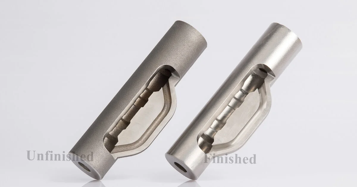
In the world of manufacturing, product surfaces often end up with irregular textures straight from the production line. As the market's appetite for top-notch quality finishes continues to surge, surface finishing has emerged as an indispensable aspect of the manufacturing process. Far from being just about looks or a smooth appearance, surface finishing plays a pivotal role in determining a product's functionality, durability, and overall performance.
Dive into our comprehensive guide to gain in-depth knowledge about surface finishing. Here, you'll discover valuable tips on how to achieve the perfect finish and how to select the most suitable surface roughness for CNC machining.
What Exactly Is Surface Finish?
Surface finish, also referred to as surface texture or surface topography, encompasses the overall smoothness, texture, and quality of a part's surface. It stands as a crucial factor in manufacturing and engineering, influencing not only how a product looks but also its performance and functionality.
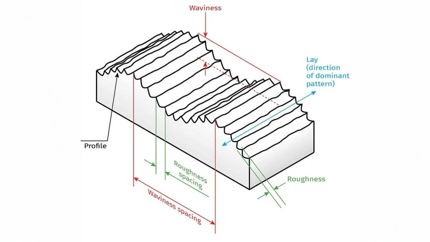
The key elements that define surface finish can be categorized into three main aspects:
Surface Roughness
Surface roughness pertains to the minute, closely spaced irregularities on a surface. These imperfections may be invisible to the naked eye but are noticeable to the touch.
Roughness is commonly quantified using parameters like Ra (average roughness). A lower Ra value indicates a surface with fewer and smaller irregularities, translating to a smoother surface that reduces friction and wear. In professional discussions, when people mention surface finish, they often specifically mean surface roughness.
Waviness
Waviness differs from surface roughness in that it involves larger, more widely spaced irregularities on the surface. These can be caused by various factors during the manufacturing process, such as machine vibrations, deflections, or warping. Surface waviness can have a significant impact on how parts fit together and their sealing capabilities.
Lay (Surface Pattern Direction)
Lay refers to the dominant direction of the surface pattern, which is typically determined by the manufacturing process used. It can be parallel, perpendicular, circular, crosshatched, radial, multi-directional, or isotropic (non-directional).
The lay direction affects aspects such as friction, lubrication, and aesthetics. In optical components, for example, a specific lay direction can reduce light scattering and enhance clarity.
Why Surface Finish Matters in Manufacturing
As previously mentioned, surface finish has a profound impact on a product's appearance, performance, durability, and overall quality. This is precisely why it holds such a critical position in the manufacturing process. Let's break down the key reasons:
Aesthetics
First impressions matter, especially when it comes to products. The appearance and tactile feel of a product often shape our initial perception. A high-quality surface finish can enhance a product's visual appeal, greatly influencing consumer satisfaction, particularly for consumer goods.
Friction and Wear
In mechanical applications, a smoother surface finish significantly reduces friction and wear between moving parts. This, in turn, minimizes heat generation and improves the efficiency and lifespan of components.
Sealing and Fitting
Proper surface finish ensures better sealing and fitting of parts, preventing leaks and enabling precise assemblies. This is crucial for the functionality of many products, from machinery to household appliances.
Fatigue Strength
Smoother surfaces enhance fatigue strength by reducing stress concentrations and the likelihood of crack initiation. This is especially important for parts that are subject to repeated loading.
Corrosion Resistance
A superior surface finish improves corrosion resistance by minimizing crevices where corrosive agents can accumulate. This helps protect the product and extend its lifespan, especially in harsh environments.
Adhesion of Coatings
The surface texture affects how well coatings or paint adhere to the product. A suitable surface finish can ensure better adhesion, resulting in a more durable and attractive finish.
Improved Conductivity and Heat Dissipation
In electronic and thermal applications, a high-quality surface finish enhances conductivity and aids in heat dissipation, ensuring optimal performance of components.
Control of Light Reflection and Scattering
In optical applications, the surface finish determines how light is reflected and scattered. This is essential for products such as lenses, mirrors, and optical sensors.
Measuring Surface Roughness
Given the critical role of surface finish in manufacturing, accurately measuring surface roughness is essential in production processes. This allows us to precisely understand the actual surface characteristics of products, ensuring they meet design and functional requirements.
Measuring surface roughness involves using various techniques and data analysis to assess the relative smoothness of a product's surface profile. The most commonly used numeric parameter for this purpose is Ra.
There are several methods available for measuring surface roughness, which can be broadly categorized as follows:
Contact Methods (Stylus Probe Instrument)
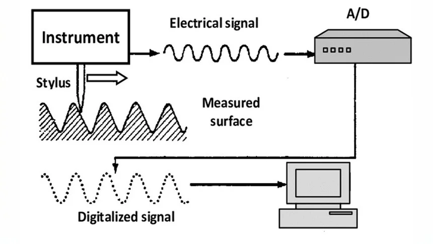
Contact methods involve physically touching the surface with a tool, such as a stylus probe instrument. This device moves vertically relative to the surface lay direction to trace the surface profile. The movement of the probe generates a detailed surface contour map, providing precise data on surface roughness.
These methods are commonly used in manufacturing settings where direct contact with the surface does not cause damage. However, they may not be suitable for delicate or soft surfaces that could be distorted by the probing action.
Non-Contact Methods (Optical Light, Laser)
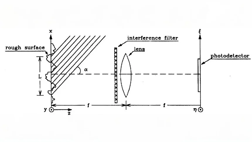
Optical Profilometer/White Light Interferometer: This technique projects a light beam onto the surface and measures the pattern of reflected light to accurately determine surface height variations, creating a detailed 3D surface profile. It is well-suited for delicate or soft surfaces in precision engineering, semiconductor, and optical industries. However, it requires surfaces with good reflective properties and the equipment can be costly.
Laser Scanning Confocal Microscopy: This method uses a focused laser beam to scan the surface, generating high-resolution 3D images of the topography. It is ideal for analyzing complex 3D surfaces in biomedical research, materials science, and precision engineering. However, it is expensive and complex to operate.
3D Laser Scanning: This technique uses a laser to capture the topography of a surface and create a 3D model. It is typically used for larger surfaces and can quickly generate a comprehensive surface profile. It is suitable for large or complex surfaces in automotive, aerospace, and architectural applications. Although it can cover large areas efficiently, it has a lower resolution compared to other methods and is not suitable for high-precision measurements of very small surface features.
Comparison Methods
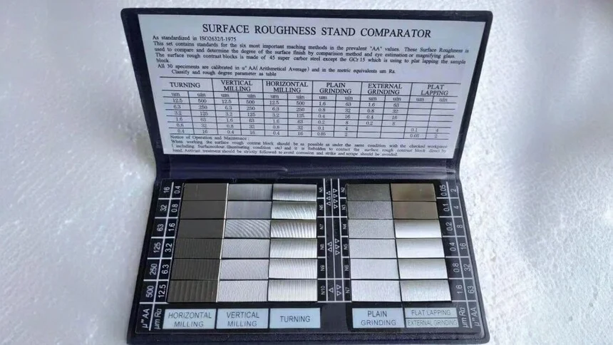
Comparison methods involve comparing the surface in question with a standard set of samples that have known roughness values.
These methods are quick and cost-effective, making them suitable for routine checks in production environments. However, they are more subjective and less suitable for applications that require high precision.
In-Process Methods
In-process methods integrate surface roughness measurement directly into the manufacturing process. Tools such as in-line profilometers or integrated sensors in CNC machines are used to provide real-time data on the surface finish, allowing for immediate adjustments.
This approach is particularly useful for real-time monitoring and quality control in continuous production lines and automated manufacturing systems. However, it may be limited in situations where integrating measurement systems into the process is not feasible due to space, cost, or complexity constraints.
When using any of these measurement methods, it's important to pay attention to the measurement unit. In the United States, micro-inches (µin) are commonly used for roughness measurement, while internationally, micrometers (µm or um) are the standard. Here are some key conversion factors:
1 µm (micrometer) = 0.000001 m (meter)
1 µin (micro-inch) = 0.000001 in (inch)
1 µm (micrometer) ≈ 39.37 µin (micro-inches)
Understanding Surface Roughness Parameters and Symbols
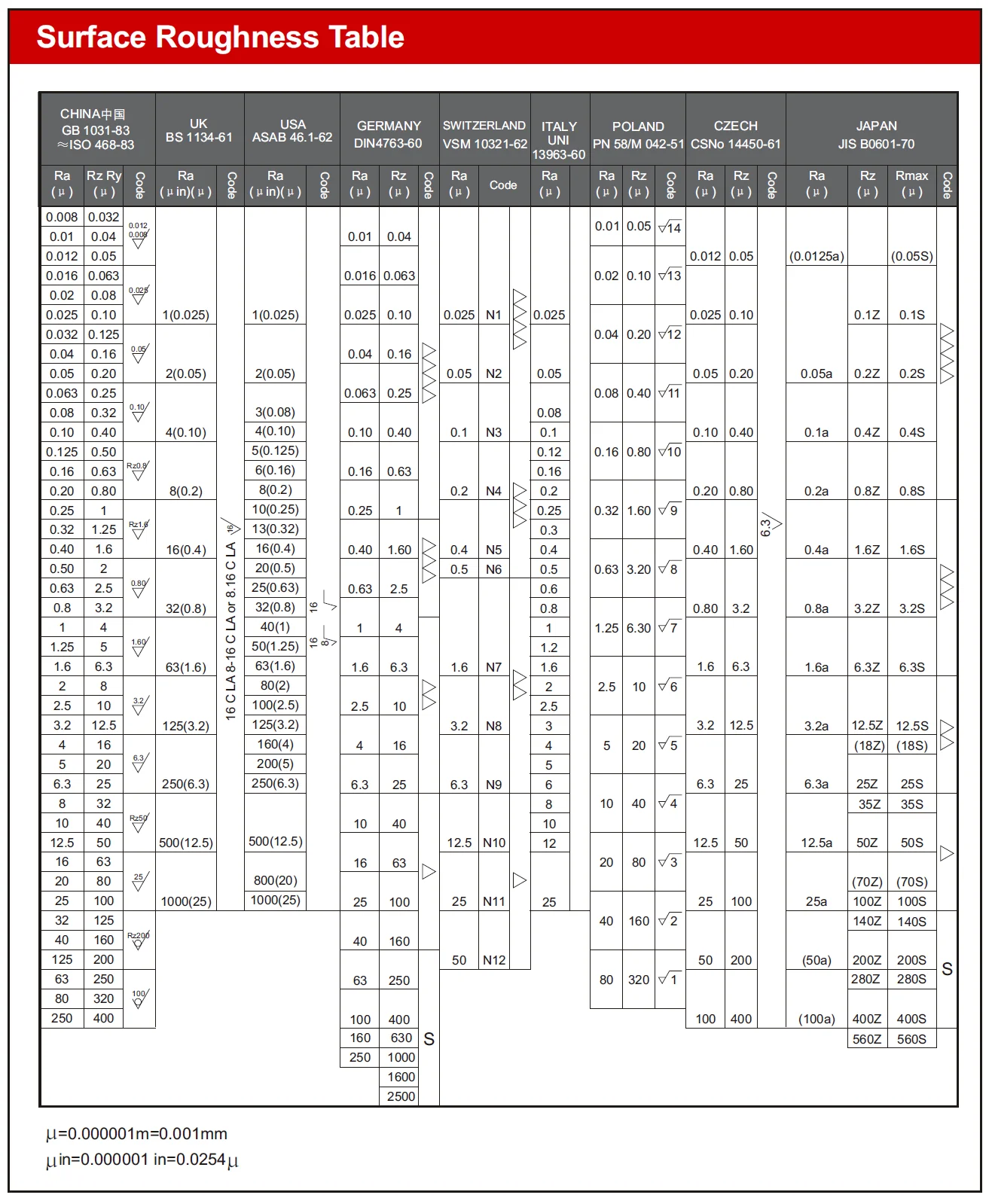
Navigating the complex world of manufacturing requires a clear understanding of the symbols and parameters in the Surface Roughness Table. These indicators act as guides, helping us ensure that surface quality, functionality, and suitability meet our expectations.
Roughness Parameters
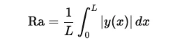
Ra: Average Roughness: Ra represents the average variation of the roughness profile from the mean line. Mathematically, it is the arithmetic average of the absolute values of the surface height deviations measured from the mean line over the evaluation length. Ra is the most widely used parameter for surface roughness as it offers a simple, general indication of the surface texture, providing a balanced view of overall roughness without being overly influenced by extreme peaks or valleys.
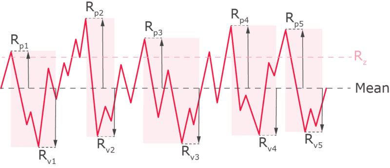
Rz: Average Maximum Height: To calculate Rz, the evaluation length is divided into five equal segments. Rz is the average of the maximum peak-to-valley heights within each of these five sampling lengths. Rz provides a more detailed picture of surface roughness compared to Ra and is more sensitive to the peaks and valleys of the surface profile. It is commonly used in industries where extreme surface texture variations are critical, such as in sealing surfaces. While an approximate formula "7.2 x Ra = Rz" is sometimes used for convenience, it is only a rough estimate.
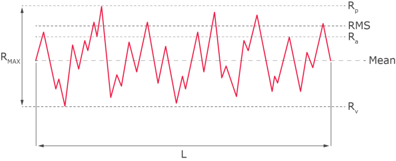
Rp: Maximum Profile Peak Height: Rp is the height of the highest single peak in the surface profile, measured from the mean line within the evaluation length.
Rv: Maximum Profile Valley Depth: Rv is the depth of the deepest single valley in the surface profile, measured from the mean line within the evaluation length.
Rt: Total Roughness: Rt represents the total vertical distance between the highest peak and the lowest valley within the entire evaluation length. It is useful for overall quality control to ensure that there are no extreme deviations in the surface.
Rmax: Maximum Roughness Depth: Rmax is the largest peak-to-valley height within the evaluation length. It focuses on the most significant localized roughness, making it valuable for applications where specific areas of the surface need strict control, such as critical sealing or contact surfaces.
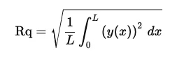
RMS: Root Mean Square Roughness: Also known as Rq, RMS is the root mean square average of the surface height deviations from the mean line over the evaluation length. It gives more weight to larger deviations compared to Ra, making it particularly useful for applications that are sensitive to significant surface variations, such as precision engineering and optical applications.
Roughness Symbols

Roughness symbols are often represented as check marks, with the point of the mark resting on the surface to be specified. For more detailed information, refer to the relevant table.
Achieving the Desired Surface Finish
In practice, numerous factors can influence the quality of a part's surface, ranging from the choice of raw materials to specific processing techniques, and even machining conditions such as tool condition and machining parameters. When the processing material is already determined, here are some strategies to obtain an ideal surface finish:
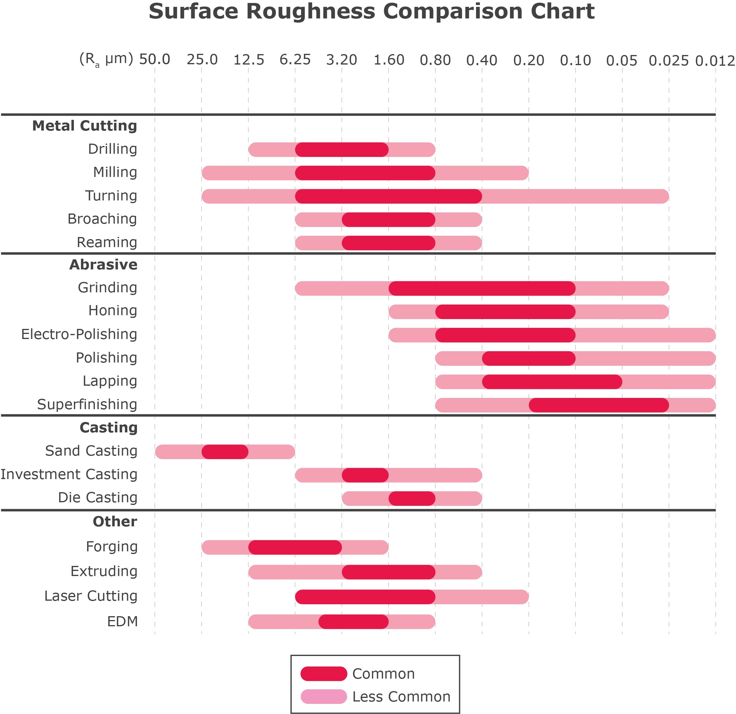
Manufacturing Process Selection: Surface finish is highly dependent on the manufacturing process used. Different processes yield varying levels of surface roughness, as illustrated in the surface roughness comparison chart.
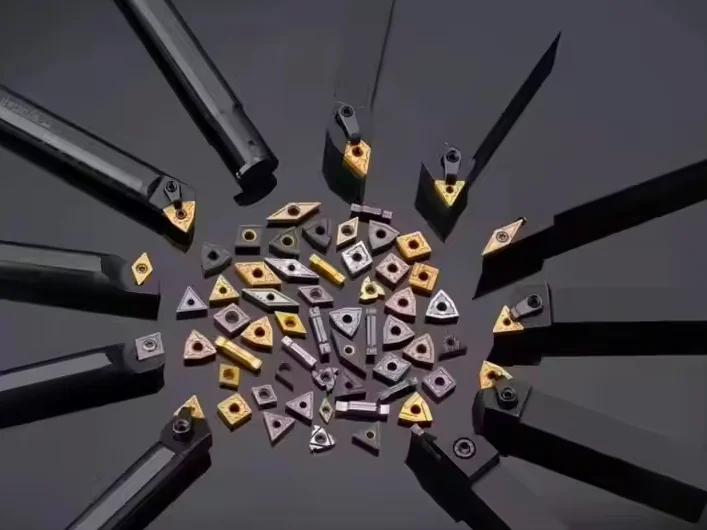
Tool Quality: Use high-quality tool materials like carbide or diamond to maintain the sharpness of cutting tools. Regularly replace worn tools to avoid rough surfaces caused by chatter and increased friction.
Machining Parameter Optimization: Optimize cutting speeds to minimize the formation of built-up edges. Employ lower feed rates and shallower cuts for a finer surface finish.
Coolant Selection: Choose appropriate coolants to reduce friction and heat at the cutting interface, which helps in achieving a better surface finish.
Professional Services: Rely on experts like HL Parts. We offer a wide range of surface finishing services, including polishing, bead blasting, and grinding, to enhance surface smoothness and meet your specific requirements.
It's important to note that achieving a smoother surface through additional processing comes at a higher cost. Therefore, engineers and designers should avoid setting overly stringent roughness requirements. Whenever possible, roughness specifications should be aligned with the capabilities of the primary manufacturing process to balance quality and cost.
Selecting the Right Surface Roughness for CNC Machining
As shown in the Surface Roughness Comparison Chart, CNC machining can produce a wide spectrum of surface roughness levels. So, how do you choose the most suitable surface roughness for your project?
In the chart, roughness grade numbers (such as N12, N11, N10, etc.) are often used in ISO 1302 to denote different levels of surface roughness. Here are some typical roughness grades for CNC machining and their applications:
Ra 3.2 µm (N8): A surface finish of Ra 3.2 µm is moderately smooth and commonly serves as a standard for commercial machinery. While it may still show visible but not excessive cutting marks, it is suitable for most consumer parts and many general applications.
Ra 1.6 µm (N7): With a Ra 1.6 µm surface finish, the surface is relatively smooth, with minimal cutting marks that are hardly noticeable. This finish is ideal for slow-moving and mildly load-bearing surfaces, such as pump parts and hydraulic components.
Ra 0.8 µm (N6): A Ra 0.8 µm surface finish indicates an extremely smooth and precise surface, making it the standard for many precision engineering applications, including aerospace and automotive components.
Ra 0.4 µm (N5): A Ra 0.4 µm surface finish offers an almost mirror-like appearance. Achieving this level of smoothness requires significant effort and cost, so it should be specified only when top-level smoothness is essential. It is typically used in optical components, scientific instruments, and other high-precision applications.
Conclusion
Surface finish is an integral part of the manufacturing process, shaped by the production methods employed. It has a far-reaching impact on a product's functionality, aesthetics, and durability. However, it's crucial to remember that a lower surface roughness isn't always better; practical considerations and budget constraints must be taken into account.
As a one-stop processing manufacturer, HL Parts is committed to meeting strict surface finish standards. We leverage a variety of manufacturing processes and surface finishing services to deliver high-quality products. Moreover, we offer cost-effective solutions tailored to your specific project needs, ensuring that you get the best balance of quality and value.
Key Takeaways
Surface finish is defined by three key characteristics: lay, waviness, and roughness. In technical drawings, roughness is often the only specified characteristic as it is the most representative parameter of surface features.
Ra (average roughness) and Rz (mean roughness depth) are the most commonly specified roughness parameters. In most cases, Ra is less than Rz, with a rough conversion estimate of Rz ≈ 7.2 x Ra.
Always pay attention to the units of roughness measurement, whether it's SI units (micrometers) or English units (micro-inches).
Smoother surfaces come at a higher cost due to additional manufacturing processes. To minimize costs, specify the roughest acceptable finish that meets your requirements.
When choosing surface roughness for CNC machining, balance functionality and cost. Ra 3.2 µm is suitable for most commercial parts, Ra 1.6 µm is good for precise, slow-moving components, Ra 0.8 µm is ideal for high-precision applications, and Ra 0.4 µm should be used only when extreme smoothness is necessary due to its high cost.
In practice, surface roughness values follow established standards. ISO standards are widely recognized globally, while ASME standards are predominantly used in the United States. ISO 4287 and ASME B46.1 focus on surface roughness measurement and evaluation, while ISO 1302 and ASME Y14.36M deal with graphical representation on technical drawings.