A Comprehensive Guide of Mastering Lathe Cutting Tools
Lathe cutting tools are essential instruments used in lathe machines, whether they are manual, woodworking, or CNC (Computer Numerical Control). These tools are designed to shape, cut, or finish rotating workpieces. Typically, a lathe cutting tool has two main parts: a shank that secures the tool to the lathe's tool post and a cutting edge that directly interacts with the workpiece. Available in a wide range of shapes, sizes, and materials, these tools can perform diverse operations such as turning, facing, threading, and parting, depending on the chosen tool paths.
The choice of the right lathe cutting tool is crucial as it directly affects the precision and efficiency of your work. In this article, we'll take a detailed look at common lathe cutting tools, explore their designs, features, and provide guidance on how to select the most suitable tool for your specific project.
Diverse Types of Lathe Cutting Tools
There are multiple ways to classify lathe cutting tools, whether based on operational requirements, tool geometry, materials, or feed direction. However, instead of delving into complex classification systems, let's focus on the basics: what these tools look like and what they can do. Understanding these two aspects is the first step towards mastering their usage.
Classification by Feed Direction
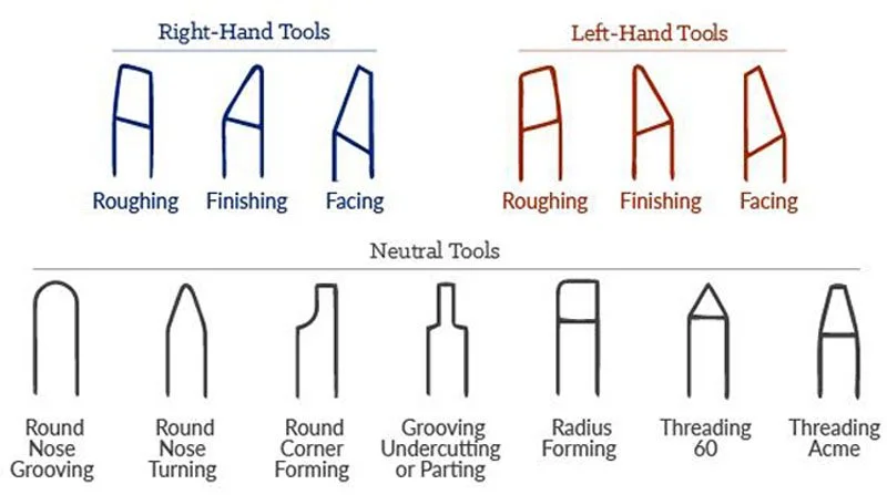
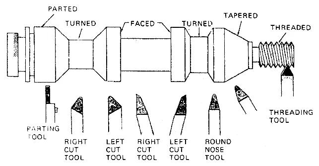
Right-Hand Cutting Tools: These tools have their main cutting edge on the left side. They cut as they move from right to left, towards the headstock of the lathe. Since most lathe operations involve feeding the tool in this direction, right-hand cutting tools are the most commonly used. They are ideal for general turning tasks, like reducing the diameter of a workpiece, facing the ends, and achieving a smooth surface finish.
Left-Hand Cutting Tools: Opposite to right-hand tools, left-hand cutting tools have their main cutting edge on the right side. They cut while moving from left to right, away from the headstock. These tools are particularly useful when machining near the tailstock or when there are obstructions on the left side of the workpiece that require the tool to be fed in the opposite direction.
Neutral Cutting Tools: Neutral cutting tools feature a symmetrically positioned cutting edge along the tool’s centerline. This design allows them to cut in both directions without the need to change orientation. They are commonly used for finishing operations or in applications where consistent cutting performance in both feed directions is necessary. However, they are less frequently employed in heavy-duty or specialized tasks compared to right-hand or left-hand tools.
Operations Performed by Lathe Cutting Tools
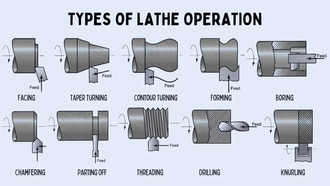
Turning Tools: Turning tools are the most widely used in lathe operations. Their primary function is to remove material along the length of a workpiece to reduce its diameter. This category includes roughing tools, which are used to quickly remove large amounts of material, and finishing tools, which make precise, fine cuts for a smooth surface.
Facing Tools: Facing tools cut perpendicular to the axis of rotation of the workpiece, creating a flat and smooth surface on its end. This operation is often carried out to prepare the workpiece for subsequent machining processes, such as drilling or threading, or to achieve the desired end dimensions of a part.
Parting Tools (Cut-Off): Parting tools usually have a thin, straight blade with a sharp cutting edge. Their main purpose is to cut through the diameter of a rotating workpiece, separating one part from the rest. Additionally, they can be used to create grooves in the workpiece when needed.
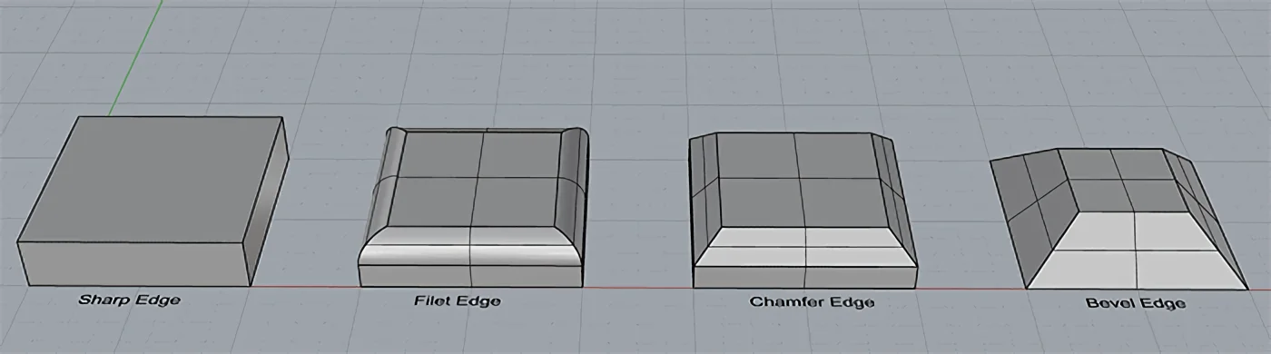
Chamfering Tools: Chamfering tools are used to cut a beveled edge, usually at a 45-degree angle, on the edges of a workpiece. This operation serves several purposes, including removing sharp edges for safety or aesthetic reasons, preparing the workpiece for further machining, or ensuring a proper fit during assembly.
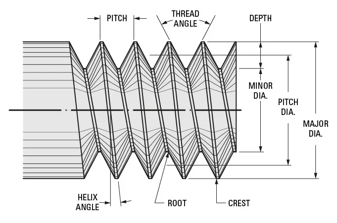
Threading Tools: Thread cutting tools are used to cut helical threads on a lathe. The shape of the thread, such as V-threads or square threads, is determined by the nose angle of the tool. These tools are categorized into external and internal thread cutting tools. External thread cutting tools are used to cut threads on the outer surface of a workpiece, like on bolts or screws, while internal thread cutting tools create threads inside a hole, as in nuts or threaded bores.
Grooving Tools: Grooving tools are designed to cut narrow grooves on the surface of a workpiece. These grooves can be external, for applications like creating shaft shoulders or retaining ring grooves, or internal, within a hole or bore, for features such as internal snap rings. They can also be used on the end face of a workpiece to create grooves perpendicular to the axis of rotation, often for face seal applications.
Knurling Tools: Knurling tools are unique among lathe cutting tools as they don't remove material. Instead, they use pressure to create a textured pattern on the workpiece’s surface, typically to improve grip or for decorative purposes.
Additional Lathe-Compatible Tools

Drilling Tools: Drilling tools are used to create holes along the center axis of a rotating workpiece. A drill bit is mounted in the lathe’s tailstock and fed into the workpiece as it rotates. Drilling is often the initial step before more precise internal machining operations, such as boring or tapping.
Boring Tools: Boring tools are used to increase the size of an existing hole in the workpiece. These single-point tools are mainly designed to enlarge and correct the hole's diameter.
Reaming Tools: Reaming involves using a multi-edged tool to finish a pre-drilled or pre-bored hole, improving both its dimensional accuracy and surface finish. Reamers don't significantly change the hole's size but rather fine-tune it for greater precision.
Tapping Tools: Unlike threading tools, tapping tools are used to cut internal threads directly in a pre-drilled hole in a single operation. A tap creates threads that allow screws or bolts to be inserted, making it a fast option for high-production threading of smaller holes where speed is more important than fine control.
Materials of Lathe Cutting Tools
Lathe cutting tools are made from materials similar to those used in milling cutter tools. Common materials include high-speed steel (HSS), carbide, ceramic, and cubic boron nitride (CBN). These materials are favored for their excellent hardness, wear resistance, and heat resistance, making them suitable for both turning and milling operations.
Diamond tools are also used in lathe cutting. Since turning is a continuous cutting process, the high hardness and wear resistance of diamond tools make them well-suited for this operation. In contrast, milling involves intermittent cutting with higher impact loads, which makes it less suitable for diamond tools. Thus, diamond tools are more commonly used in lathe operations.
Components of a Lathe Cutting Tool
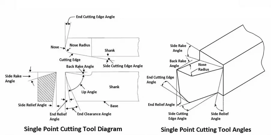
Most lathe cutting tools, regardless of their type, consist of several key components, each playing a crucial role in how the tool interacts with the workpiece during the cutting process. Let's take a single-point cutting tool as an example to understand these components better.
Shank: This is the main body of the cutting tool that is clamped into the lathe’s tool holder. It secures the tool in place, transmits cutting forces, and provides structural support.
Cutting Edge: The cutting edge is the sharpened part of the tool that directly removes material from the workpiece through shearing. In single-point cutting tools, it includes the side cutting edge and the end cutting edge. The cutting edge can be an integral part of the tool or a replaceable insert made from materials like HSS, carbide, or ceramic, which affects the tool's performance and suitability for different tasks.
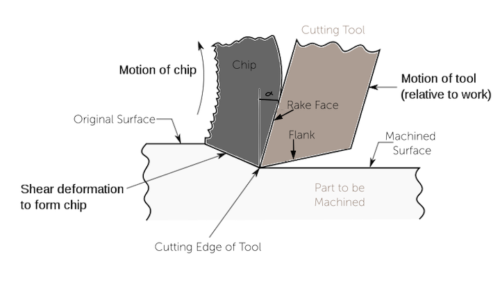
Rake Face: The rake face is the surface of the cutting tool that comes into direct contact with the material being cut. It guides the chip away from the workpiece during machining and significantly impacts cutting efficiency, chip formation, and tool wear. The rake angle, which is the angle of the rake face, can greatly affect cutting forces and the quality of the machined surface.
Flank: The flank is the surface opposite the rake face and faces the newly machined surface. It provides clearance to prevent friction between the tool and the workpiece, reducing tool wear and ensuring smooth cutting. The flank has a side flank and an end flank, and the angles between them and the workpiece (side relief angle and end relief angle) help maintain proper clearance during cutting, preventing rubbing and extending tool life.
Tool Nose: The tool nose is the rounded tip where the side cutting edge and end cutting edge meet. The nose radius affects the surface finish and strength of the cutting edge. A larger radius can enhance the surface finish but may reduce the sharpness of the edge.
Side Rake Angle: This is the angle between the rake face and a horizontal plane parallel to the workpiece surface. It influences how the chip flows away from the cutting zone. A positive side rake angle reduces cutting forces and improves chip removal, while a negative or zero side rake angle can increase cutting forces but may strengthen the cutting edge.
Back Rake Angle: The back rake angle is the angle between the rake face and a horizontal plane parallel to the workpiece surface, measured along the main cutting edge. It affects cutting forces and chip flow, determining how easily the tool can cut into the material. Adjusting this angle is important for optimizing tool performance based on the workpiece material.
Side Relief Angle: The side relief angle is the angle between the flank and a vertical plane perpendicular to the workpiece surface, measured along the side cutting edge. It provides clearance to prevent friction during side-cutting operations, ensuring smoother cutting and reducing tool wear. The right side relief angle is essential for reducing tool wear, improving cutting performance, and achieving a good surface finish.
End Relief Angle: The end relief angle is the angle between the flank and a plane perpendicular to the workpiece surface, measured along the end cutting edge. It provides clearance during end-cutting operations, enhancing cutting efficiency and surface finish. An improper end relief angle can lead to excessive friction, heat, or weakened cutting edges.
End Cutting Edge Angle: This angle is between the tool's end cutting edge and a line perpendicular to the workpiece surface. It influences chip flow direction and cutting forces. A larger angle reduces cutting forces and improves chip flow, increasing tool life but may cause more deflection. A smaller angle strengthens the cutting edge but can increase cutting forces and wear.
Side Cutting Edge Angle: The side cutting edge angle is between the tool’s side cutting edge and a line parallel to the workpiece surface. It affects cutting force direction, chip formation, tool strength, and surface finish. A larger angle spreads the cutting load, reducing forces and improving the surface finish but may weaken the edge, while a smaller angle concentrates forces, potentially increasing wear but aiding in material removal in some cases.
Selecting the Ideal Lathe Cutting Tool
Choosing the right lathe cutting tool requires careful consideration of several factors, including the machining operation, tool geometry, material of the tool and workpiece, and cutting conditions. Here are some useful tips to help you make the best choice:
Match the Tool to the Operation: Different lathe operations require specific tools. For instance, turning tools are for removing material along the length of a workpiece but aren't suitable for forming operations. Also, consider the cutting direction when selecting the tool.
Consider Workpiece and Tool Material: The hardness and other mechanical properties of the workpiece will influence the choice of tool material. HSS tools may be sufficient for softer materials like aluminum, while carbide or ceramic tools are more appropriate for harder materials such as stainless steel or hardened alloys. The cutting edge material must be able to withstand the mechanical and thermal stresses generated during machining. Coatings like TiN or TiAlN can enhance tool life and performance by increasing hardness and wear resistance.
Evaluate Tool Geometry: Rake and relief angles are crucial as they must be suitable for the operation and workpiece material. They help minimize friction and wear while ensuring proper chip formation and removal. For example, a high back rake angle is beneficial for softer materials to improve chip flow, while a more neutral angle may be needed for harder materials to reduce tool wear.
Factor in Cutting Conditions: Cutting speed, feed rate, and depth of cut also play a role in tool selection. Tools like carbide or ceramic, designed for high-speed applications, can handle faster cutting speeds without degrading. If your operations involve slow feed rates or shallow cuts, a tool with a smaller nose radius or a higher rake angle might improve the surface finish.
Weigh Cost and Tool Life: While high-performance tools like carbide and diamond may have a higher upfront cost, their durability and ability to handle a wide range of materials and cutting conditions can reduce downtime and the need for frequent tool changes. In the long run, this can make them more cost-effective, especially for heavy production use.
Work with HL Parts in Lathe Cutting Project

In conclusion, lathe cutting tools are vital for achieving precision and efficiency in various machining operations. Understanding the different types of tools, their components, and how they relate to specific lathe operations is key to making informed tool selection decisions. Whether you're engaged in turning, facing, threading, or boring, the right lathe cutting tool can significantly impact the quality, speed, and cost-effectiveness of your project.
At HL Parts, our experienced engineers are ready to assist you in choosing the best lathe cutting tools for your CNC turning projects. From rapid prototyping to on-demand machined parts, we offer high-quality solutions tailored to your requirements. Simply upload your CAD files today to receive an instant quote and a free DFM analysis.