How does a Harmonic Drive operate?
One of the key benefits of a harmonic drive is its freedom from backlash, all thanks to its distinctive design. Additionally, its lightweight and highly compact nature is another significant advantage. It can achieve high gear reduction ratios, up to 30 times those of planetary gears, within the same space.
Clarence Walton Musser developed strain wave gearing back in 1957, and by 1960, he had started selling licenses, enabling industry leaders to utilize his patented product.
The harmonic drive is a type of gear system, often known as a strain wave gear due to its operational principle. It is a reduction gear mechanism that comprises at least three main components. These components work together to deliver extremely high-precision reduction ratios, which would otherwise demand more complex and bulky mechanisms.
As a product, the harmonic drive was invented by American engineer Clarence Walton Musser in 1957. It soon gained popularity in the industry because of the numerous advantages it offered. Musser recognized the potential of his invention early on. In 1960, he began granting licenses to manufacturers, allowing them to use his patented product. Currently, only a small number of manufacturers in the USA, Germany, and Japan hold the licenses to produce harmonic drives. They manufacture these drives in their state-of-the-art facilities, producing top-quality strain gears for the global market.
The Operating Principle of a Harmonic Drive
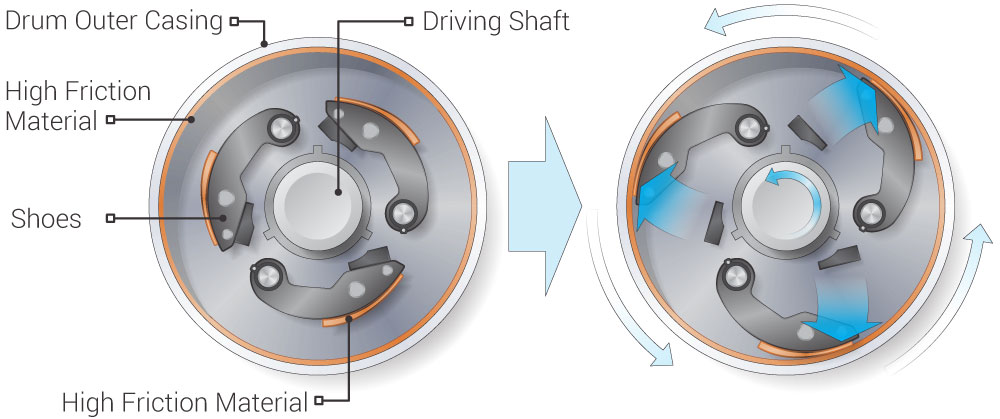
Rotational motion originates from an input shaft, such as a servo motor axis. This shaft is connected to a component called the "wave generator," which has an elliptical shape and is surrounded by an elliptical ball bearing. When the shaft rotates, the edges shift positions, creating a wave-like motion. This part is inserted into a flex spline, made of a material that is torsionally rigid yet flexible. The material adapts to this wavy motion by bending as the input shaft rotates, taking on an elliptical shape. The outer edge of the flex spline is equipped with gear teeth capable of transmitting heavy loads effectively. To transfer these loads, the flex spline is placed inside the circular spline—a round gear with internal teeth. This outer ring is rigid, and its internal diameter is slightly larger than the major axis of the ellipse formed by the flex spline. As a result, the circular spline does not adopt the elliptical shape of the other two components. Instead, its internal teeth mesh with those of the outer side of the flex spline, causing the flex spline to rotate.
The rotation speed depends on the rotation of the input shaft and the difference in the number of teeth between the flex spline and the circular spline. The flex spline has fewer teeth than the circular spline, so it rotates at a much lower ratio and in the opposite direction to the input shaft. The reduction ratio is calculated as: (number of flex spline teeth – number of circular spline teeth) / number of flex spline teeth. For instance, if the flex spline has 100 teeth and the circular spline has 105, the reduction ratio is (100 – 105) / 100 = -0.05. The negative sign indicates that the flex spline rotates in the opposite direction. The difference in the number of teeth can be adjusted to meet different reduction ratio requirements and specific application needs.
Advantages
·It can achieve reduction ratios of 1/100 and even up to 1/300 with a compact and lightweight gear setup, which is unmatched by other gear types.
·The harmonic drive is the only gear system that has no backlash or recoil effect, or they are practically negligible. This is mainly due to the elliptical bearing installed on the outer edge of the input shaft, which allows the flex spline to rotate freely.
·It has exceptional positional accuracy even after a large number of repetitions.
·It can rotate forward and backward without any adjustments and maintains the same positional accuracy in both directions.
·The efficiency of a typical harmonic drive, as tested by manufacturers in real shaft-to-shaft tests, can reach up to 90%. Few mechanical engineering components can boast such a high operational efficiency.
Applications of Harmonic Drives
In essence, harmonic drives can be used "in any gear reduction application that requires small size, low weight, zero backlash, very high precision, and high reliability". Examples include aerospace applications, robotics, electric vehicles, medical X-ray and stereotactic machines, milling and lathe machines, flexographic printing machines, semiconductor equipment, optical measuring machines, woodworking machines, and camera head pan and tilt axes. Some notable applications are the wheels of the Apollo Lunar Rover and the winches of the Skylab space station.
Conclusion
At HL Parts, we specialize in providing mechanical machining drive services that are designed to meet your specific needs and help you stay ahead in a competitive market. Upload your file and let’s get started!